Line Coding
Line Coding
Line
coding is the process of converting digital data to digital signals. We assume
that data, in the form of text, numbers, graphical images, audio, or video, are
stored in computer memory as sequences of bits. Line coding converts a sequence
of bits to a digital signal. At the sender, digital data are encoded into a
digital signal; at the receiver, the digital data are recreated by decoding the
digital signal. Below figure shows the process.

Common Characteristics
Signal Element versus Data
Element
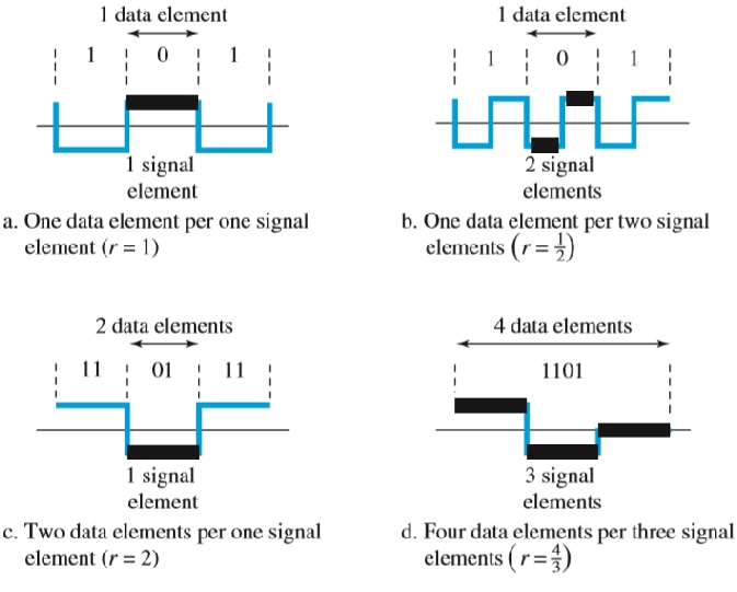
Let us
distinguish between a data element and a signal element. In data
communications, our goal is to send data elements. A data element is the
smallest entity that can represent a piece of information: this is the bit. In
digital data communications, a signal element carries data elements. A signal
element is the shortest unit (timewise) of a digital signal. We define a ratio
r which is the number of data elements carried by each signal element. Below figure shows several situations with different values of r.
Data
Rate Versus Signal Rate
The
data rate defines the number of data elements (bits) sent in 1second. The unit
is bits per second (bps). The signal rate is the number of signal elements sent
in 1s. The unit is the baud. There are several common terminologies used in the
literature. The data rate is sometimes called the bit rate; the signal rate is
sometimes called the pulse rate, the modulation rate, or the baud rate.
Line Coding Schemes
Roughly divide line coding
schemes into five broad categories.

Unipolar Scheme
In a unipolar scheme, all the
signal levels are on one side of the time axis, either above or below.
NRZ (Non-Return-to-Zero)
A
unipolar scheme was designed as a non-return-to-zero (NRZ) scheme in which the
positive voltage defines bit 1 and the zero voltage defines bit 0. It is called
NRZ because the signal does not return to zero at the middle of the bit. Below figure
shows a unipolar NRZ scheme.

Polar Schemes
In
polar schemes, the voltages are on both sides of the time axis. For example,
the voltage level for 0 can be positive and the voltage level for 1 can be
negative.
Non-Return-to-Zero
(NRZ)
Polar
NRZ encoding, use two levels of voltage amplitude. Here two versions of polar NRZ: NRZ-L and NRZ-I. The figure also shows
the value of r, the average baud rate, and the bandwidth. In the first
variation, NRZ-L (NRZ-Level), the level of the voltage determines the value of
the bit. In the second variation, NRZ-I (NRZ-Invert), the change or lack of
change in the level of the voltage determines the value of the bit. If there is
no change, the bit is 0; if there is a change, the bit is 1.

Return-to-Zero (RZ)
The
return-to-zero (RZ) scheme, which uses three values: positive, negative, and
zero. In RZ, the signal changes not between bits but during the bit. Below
Figure see that the signal goes to 0 in the middle of each bit. It remains
there until the beginning of the next bit. The main disadvantage of RZ encoding
is that it requires two signal changes to encode a bit and therefore occupies
greater bandwidth.

Biphase: Manchester and
Differential Manchester
The
idea of RZ (transition at the middle of the bit) and the idea of NRZ-L are
combined into the Manchester scheme. In Manchester encoding, the duration of
the bit is divided into two halves. The voltage remains at one level during the
first half and moves to the other level in the second half. The transition at
the middle of the bit provides synchronization. Differential Manchester, combines
the ideas of RZ and NRZ-I. There is always a transition at the middle of the
bit, but the bit values are determined at the beginning of the bit. If the next
bit is 0, there is a transition; if the next bit is 1, there is none.

Bipolar Schemes
Bipolar
encoding (sometimes called multilevel binary), there are three voltage levels:
positive, negative, and zero. The voltage level for one data element is at
zero, while the voltage level for the other element alternates between positive
and negative.
AMI and Pseudoternary
Two
variations of bipolar encoding: AMI and pseudoternary. A common bipolar
encoding scheme is called bipolar alternate mark inversion (AMI). In the term
alternate mark inversion, the word mark comes from telegraphy and means 1. So
AMI means alternate 1 inversion. A neutral zero voltage represents binary 0.
Binary 1s are represented by alternating positive and negative voltages. A
variation of AMI encoding is called pseudoternary in which the 1 bit is encoded
as a zero voltage and the 0 bit is encoded as alternating positive and negative
voltages.

Multilevel
Schemes
The
desire to increase the data rate or decrease the required bandwidth has
resulted in the creation of many schemes. The goal is to increase the number of
bits per baud by encoding a pattern of m data elements into a pattern of n
signal elements.
2B1Q
The
first mBnL scheme we discuss, two binary, one quaternary (2B1Q), uses data
patterns of size 2 and encodes the 2-bit patterns as one signal element
belonging to a four-level signal. In this type of encoding m = 2, n = 1, and L
= 4 (quaternary). Below Figure shows an example of a 2B1Q signal.

A
very interesting scheme is eight binary, six ternary (8B6T). This code is used
with 100BASE-4T cable.

Multitransition: MLT-3
The
multiline transmission, three-level (MLT-3) scheme uses three levels (+V, 0,
and −V) and three transition rules to move between the levels.
1.
If
the next bit is 0, there is no transition.
2.
If
the next bit is 1 and the current level is not 0, the next level is 0.
3.
If
the next bit is 1 and the current level is 0, the next level is the opposite of
the last nonzero level.
Summary of Line Coding Schemes

Comments
Post a Comment